Case study · Motor node · Render
From files to a closed device.
Scroll through what happens to a design, using the Motor node case study, our own design, not a customer's. Every number on screen comes from our own code: the fit check, the case the designer generates, and the rate card.
B.1
Your design, read.
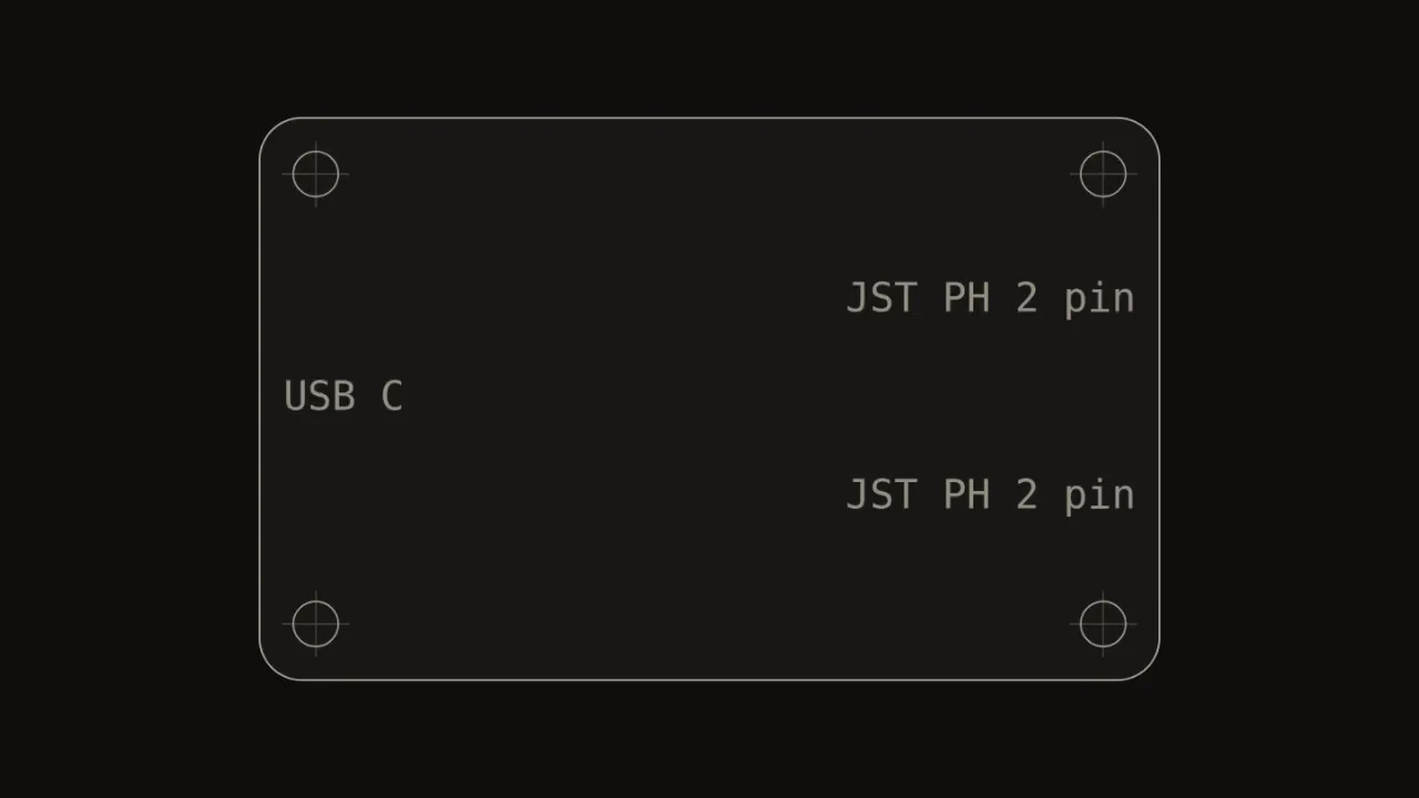
The outline, the holes, and each connector are read from the design, and this top view is drawn from it by our geometry code, not by hand. For the fit check, a board file alone gives the outline and holes only.
Board 64.0 × 40.0 × 1.6 mm · 4 holes · 3 connectors
Buyer question: Will it work with my files?
Fig. B.1Your design, read, Drawing, Units mm
Drawing · Board top view, generated from the design file
- Thickness 1.6 mm
- 4 holes, Ø3.2 mm
- 3 connectors
B.2
Apart, with dimensions.
Board, base, and lid separate. The cavity, the clearance, and the standoffs get their dimension lines, and the stack is measured against the depth.
Cavity 66.0 × 42.0 × 13.6 mm · 1.0 mm a side · Standoffs 4.0 mm
The stack needs 11.6 mm and the cavity offers 13.6 mm. 4 of 4 holes sit on a standoff.
Buyer question: Will it fit?
Fig. B.2Apart, with dimensions, Render, Units mm
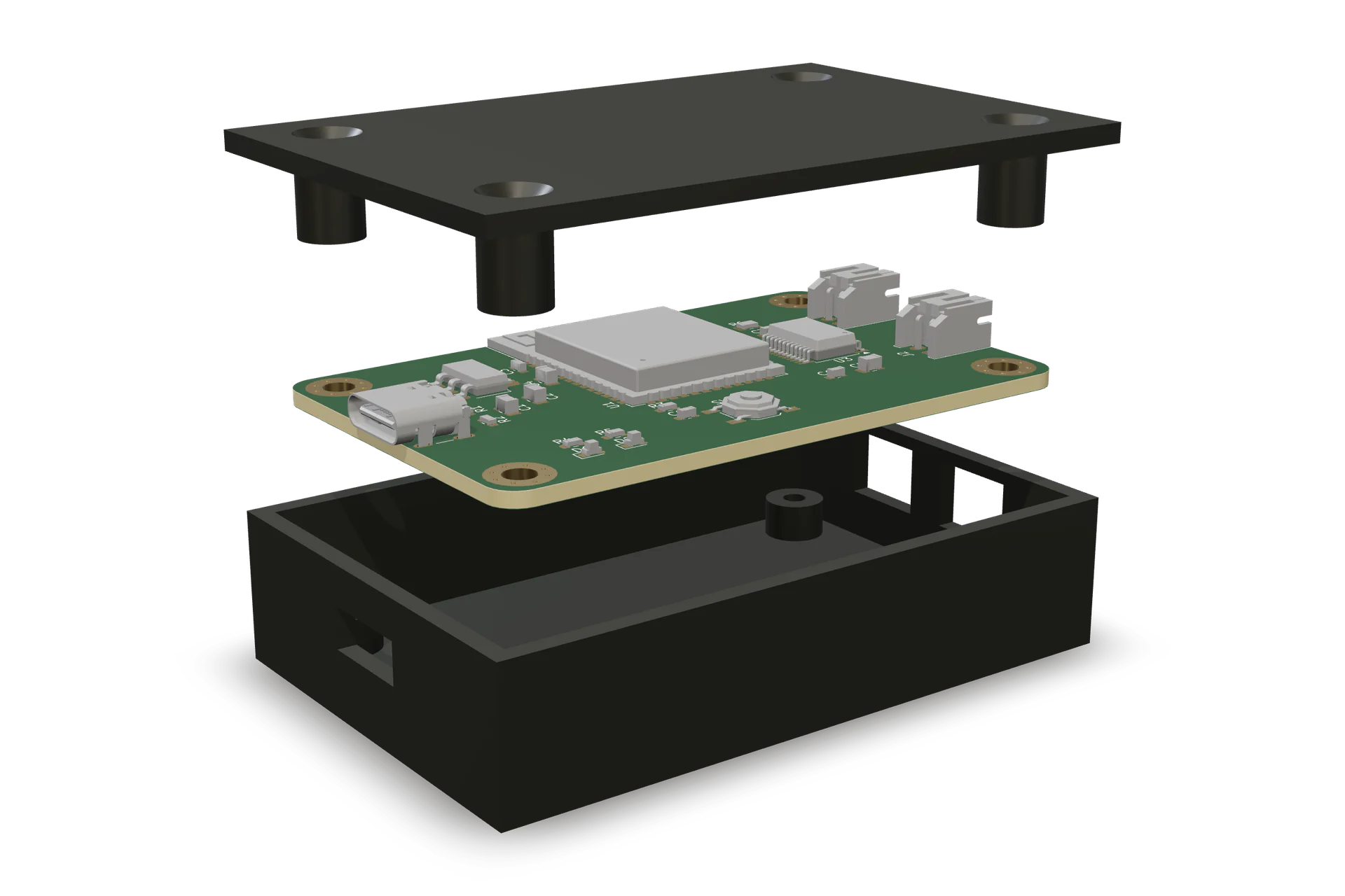
Render · Exploded view, made from the case study files
- Cavity 66.0 × 42.0 mm
- Depth 13.6 mm
- Clearance 1.0 mm a side
- Standoffs 4.0 mm
- Wall 2.0 mm
B.3
The catch.
In an earlier case, the USB C opening sat 2.3 mm off center from its connector, where 0.75 mm is allowed, and the fit check failed it. The case is generated again from the design, and the opening lines up.
- FAILOpening 2.3 mm off center · 0.75 mm allowed · 3 of 4 checks pass
- PASSOpening within 0.75 mm · 4 of 4 checks pass
The solid model check agrees: the connector overlaps 1.02 cubic mm of wall before the fix and 0.0 cubic mm after.
A worked example on our own design, not a customer order. The earlier case is this case with its USB C opening moved along the left wall.
Buyer question: Will it fit?
Fig. B.3The catch, Render, Units mm
Render · Exploded view, closer on the left wall. The outlines mark the USB C opening of the earlier case and of the corrected case, projected onto the render from the case geometry.
- FAILBefore · 2.3 mm off center
- Allowed · 0.75 mm
- Opening 10.5 × 4.4 mm
- PASSAfter · within 0.75 mm
B.4
A price you approve.
PCB fabrication, parts, the case, hand assembly, our service line, and the operator review, priced on the rate card for 10 units of this design and added up to one number. The operator confirms or revises it before you approve anything.
Rate card estimate · $444.63 for 10 units · $44.46 a unit
Range $233.16 to $1,465.68.
An estimate, not a quote. The number the operator sends you is the quote.
Buyer question: What does it cost?
Fig. B.4A price you approve, Engine output
Rate card estimate · 10 units
$444.63
$44.46 a unit, Range $233.16 to $1,465.68
Engine output · The rate card lines for 10 units of the case study design.
B.5
Closed.
The board drops onto its standoffs and the lid goes on, with 4 countersunk holes for its screws. All 3 openings line up with their connectors.
Closed 70.0 × 46.0 × 17.6 mm · 4 lid screws
Buyer question: Do I get a real thing?
Fig. B.5Closed, Render, Units mm
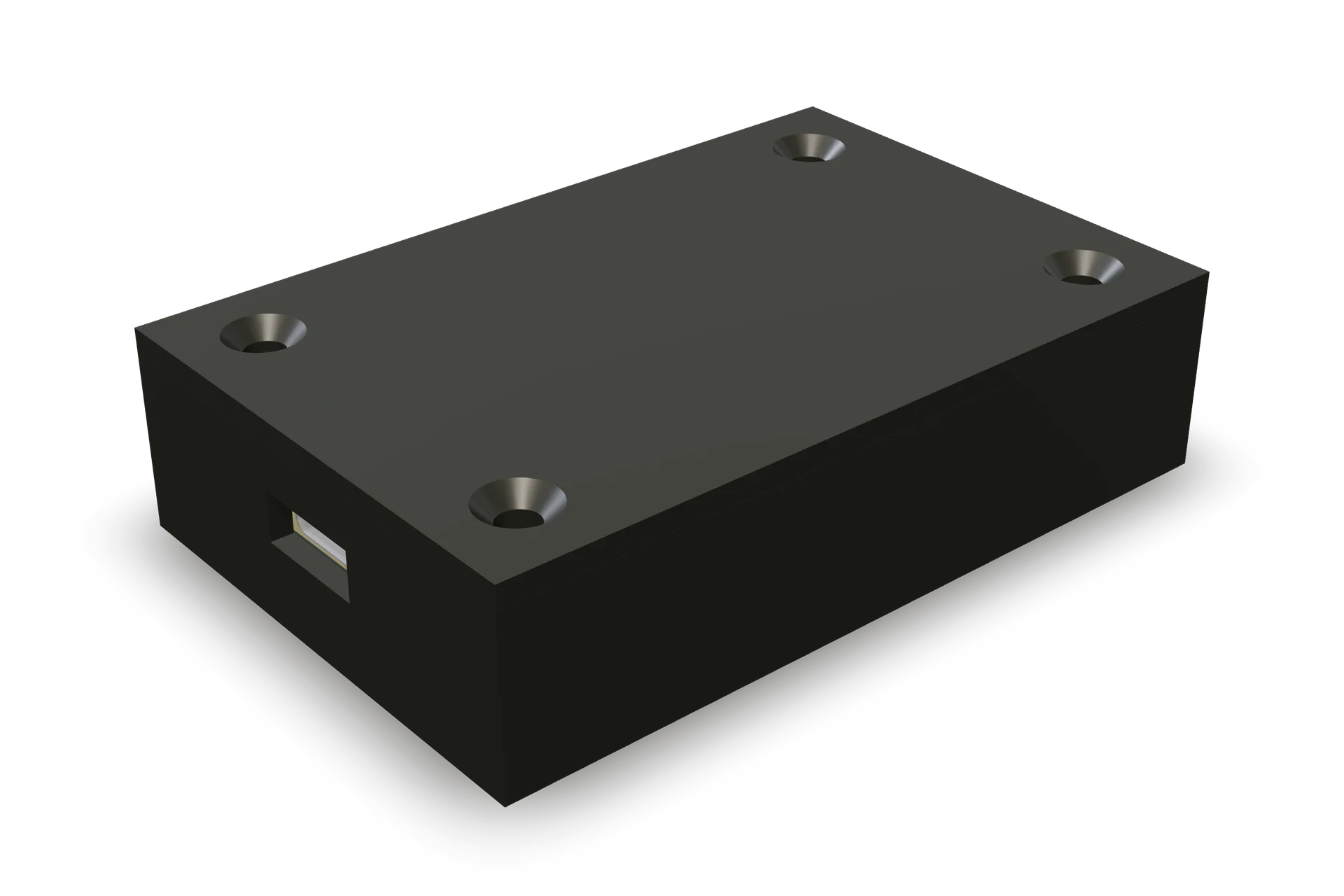
Render · The closed case, made from the case study files
- 70.0 × 46.0 × 17.6 mm
- 4 lid screws
B.6
Not built yet.
This is a render of the case study files, not a photograph. When the first real unit is built, its photo goes here.
Render · No photo yet
Buyer question: Do I get a real thing?
Fig. B.6Not built yet, Render
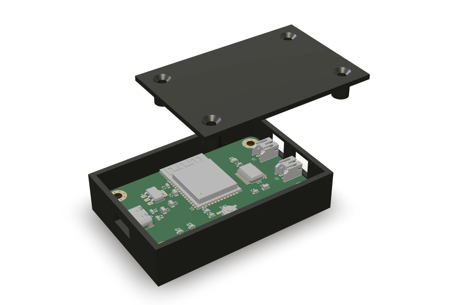
Motor node case study, rendered from its files. Not a photograph. A photo replaces it once a real unit is built.